Industrial equipment often faces load spikes, slow startups, and uneven torque demands that place stress on motors and drive components. These issues lead to heat buildup, premature wear, and stalled production lines. Many plants also deal with aging gear drives or mismatched reducers that no longer support current load requirements.
OEMs see similar problems when equipment must meet tighter performance standards with limited motor power. These challenges push engineers and maintenance teams to review torque management and gearbox selection more carefully.
This guide highlights the principles and practical factors that influence torque reduction, gearbox performance, and consistent plant output.
Key Takeaways
Torque-reduction gearboxes increase torque output while reducing motor speed, for smoother, safer, and more efficient operation.
They are essential for heavy-duty industrial applications like conveyors, mixers, packaging machines, and material-handling systems.
Key selection factors include load requirements, desired output speed, duty cycle, mounting style, and environmental conditions.
Proper sizing and configuration prevent wear, overheating, and energy loss, improving equipment life and reliability.
Midwest Power Products offers a wide range of compatible gearboxes and expert guidance to help you choose the right solution.
Torque Reduction Gearbox: Core Function and Purpose
A torque-reduction gearbox reduces input speed and increases output torque, allowing equipment to handle heavier loads without oversizing the motor. These gearboxes support applications that need controlled motion, steady force, and reliable output during frequent starts, continuous cycles, or high-load conditions.
Key functions include:
Lowering motor speed to match equipment requirements
Increasing output torque for load-handling
Managing shock loads and resisting wear during demanding cycles
Supporting long service life with proper lubrication and alignment
To understand this function more precisely, it helps to look at how gear ratios determine the balance between output speed and torque.
How Gear Ratios Shape Torque Output and Speed Reduction
Gear ratio defines how input rotation is converted into output speed and torque. A higher gear ratio reduces output speed while raising torque.
Fundamental relationship:
Higher gear ratio → lower output speed
Lower output speed → higher torque
A simple example is a small input gear driving a larger output gear. The larger gear turns more slowly but delivers greater torque. This principle helps equipment start under load, move heavy material, and maintain steady performance in systems where torque demand exceeds motor capacity.
Now, let’s look at the internal mechanics that make speed reduction and torque multiplication possible.
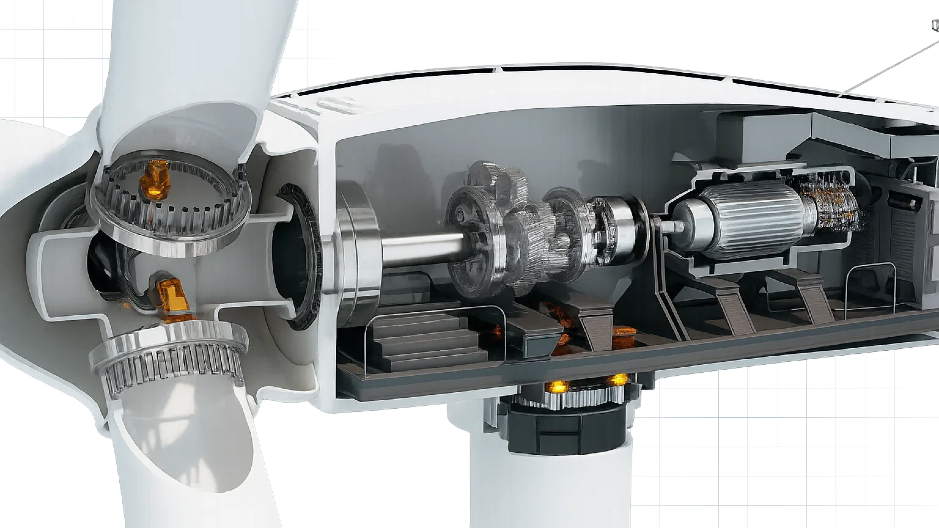
Mechanics That Convert Motor Speed Into Usable Torque
A gearbox increases torque through the mechanical advantage created by the gear arrangement and the difference in gear diameters or tooth counts.
How this process works:
Input shaft: receives fast rotation from the motor
Gear train: transfers motion through gear sets sized to reduce speed
Output shaft: delivers reduced speed and higher torque
Mechanical advantage: achieved through gear ratio differences
This torque gain enables conveyors, mixers, pumps, and other industrial machines to operate under load without stalling or overheating the motor. Now, the next question is why it’s needed across different industrial applications.
Why Torque Reduction Is Needed in Industrial Machinery
Torque reduction protects equipment, improves precision, and keeps motors operating safely. Start-up loads, heavy-duty tasks, and precision applications all require controlled torque for consistent performance.
Starting loads (conveyors, mixers, agitators): These machines face high resistance during startup. Torque reduction prevents sudden shocks and allows equipment to accelerate gradually without stressing components.
Heavy-duty operation (crushers, shredders): Material-handling machinery encounters unpredictable load spikes. Controlled torque protects the system from jamming and minimizes wear during heavy or uneven loads.
Precision control (packaging, bottling, robotics): Applications requiring accurate, repeatable movements benefit from torque reduction because it eliminates abrupt force changes and ensures smooth, stable motion.
Protecting motors from overload: Controlled torque keeps motors within safe load limits, preventing overheating, stalling, or electrical overload while reducing maintenance needs.
Energy efficiency and smoother operation: Limiting unnecessary torque helps optimize power consumption, reduce vibrations, and improve overall machine performance, resulting in lower operating costs.
Next, let’s explore how industrial gearboxes deliver speed control, torque multiplication, and reliable motion.
Essential Roles of Gearboxes in Industrial Machinery Performance
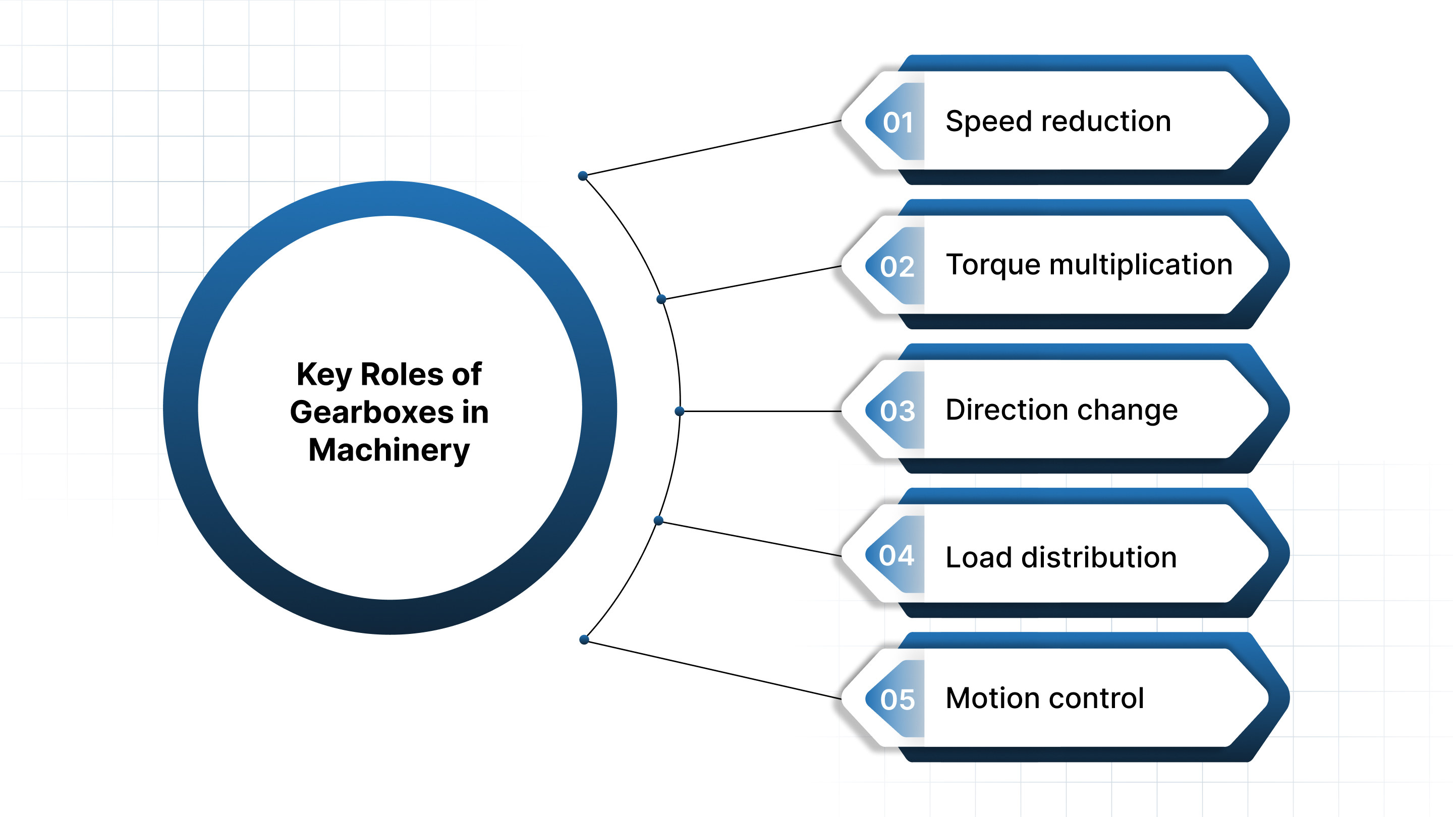
An industrial gearbox does far more than slow down rotational speed. It ensures machines operate with the right force, direction, and stability needed for continuous industrial duty cycles. These core functions directly influence equipment life, energy use, and process consistency.
Speed reduction: Gearboxes reduce high motor RPM to the lower speeds required by conveyors, mixers, crushers, and other load-driven equipment.
Torque multiplication: By lowering speed, the gearbox increases output torque — giving machines the force needed to start, lift, press, or crush without overloading the motor.
Direction change: Gear arrangements can reverse rotation or redirect it at 90°, enabling flexible machine layouts and custom motion requirements.
Load distribution: Proper gear design spreads mechanical load across gears and shafts, reducing stress on the motor and increasing the system’s reliability.
Motion control: Gearboxes stabilize output speed and torque, ensuring smooth, predictable movement for precision applications like packaging, dosing, and robotics.
Gearboxes perform essential roles in controlling speed, torque, and load; selecting the right type ensures these roles are executed effectively.
Types of Torque Reduction Gearboxes and Speed Reducers
Industrial applications rely on several reducer designs, each suited to specific load levels, duty cycles, and mounting needs. The options below cover the most commonly used torque-reduction systems in plants, material-handling setups, and OEM equipment.
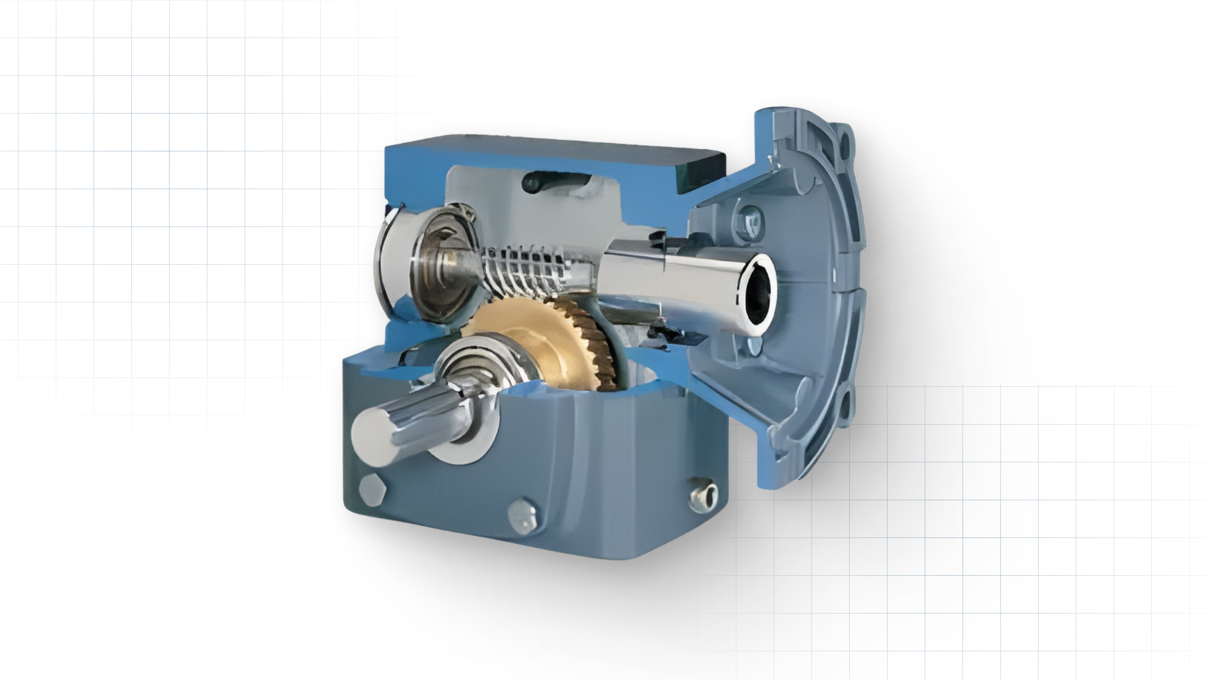
Worm reducers use a worm shaft and worm wheel that mesh at an angle, creating high ratios in a compact housing.
High reduction ratios: Ideal where large speed drops are needed in limited space.
Strong low-speed torque: Useful for starting heavy conveyor sections or indexing equipment.
Quiet and compact: Common in packaging lines, light conveyors, and moderate-load machinery.
Helical Gear Reducers (Inline / Parallel Shaft)
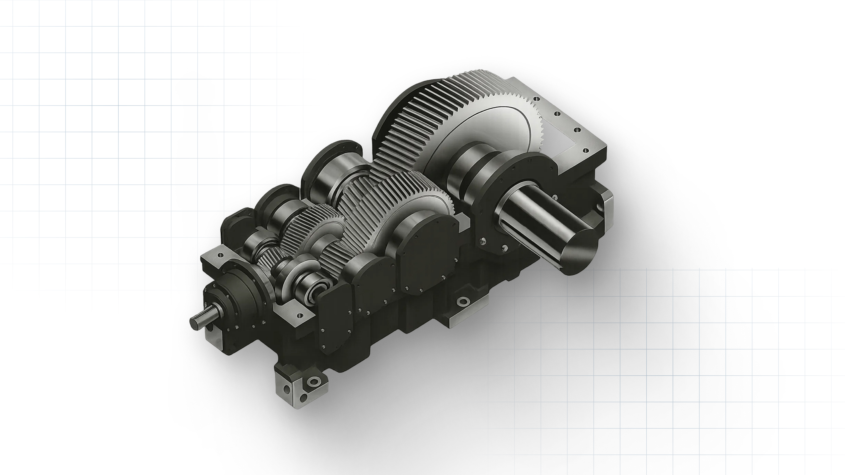
Helical gears provide smooth contact due to their angled teeth, making them efficient and reliable for long duty cycles.
High efficiency: Less heat and power loss compared to worm drives.
Consistent torque delivery: Suited for fans, pumps, mixers, and other continuous-run units.
Inline or parallel options: Helps match space constraints and shaft configurations.
Bevel Gear and Spiral Bevel Reducers
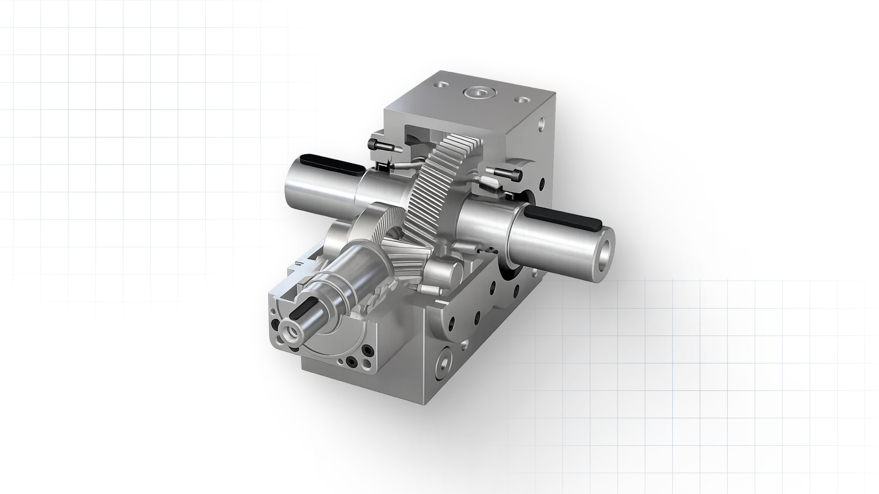
Bevel reducers shift power at right angles without losing torque strength.
90° direction change: Simplifies equipment layouts and corner transitions.
Durable under load: Handles mixers, agitators, and rugged industrial drives.
Spiral bevel variants: Offer smoother, more stable torque transfer for heavy loads.
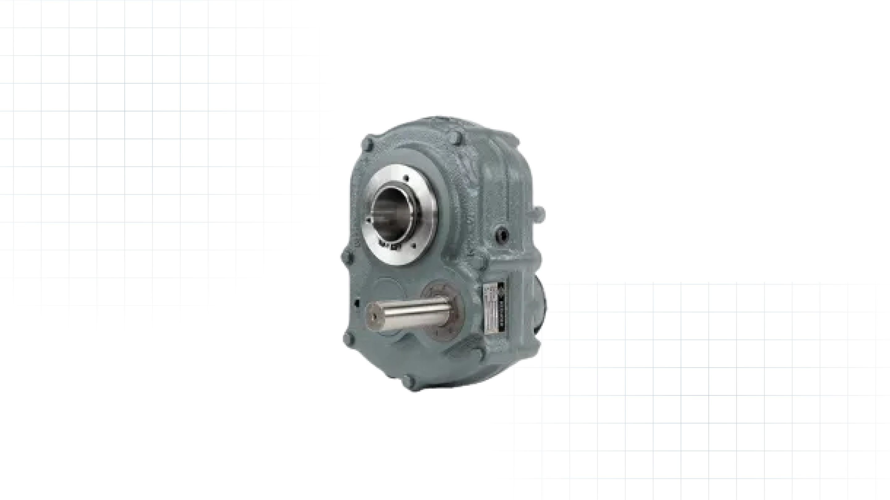
These units mount directly on the driven shaft, reducing alignment work and installation time.
Fast installation: No base plate or extra coupling needed.
Ideal for conveyor systems: Heavily used in mining, cement, aggregates, and bulk material handling.
Low-maintenance design: Fewer alignment issues during long-term operation.
Planetary Gearboxes
Planetary designs use multiple planet gears around a central sun gear, spreading the load across several contact points.
Very high torque density: Delivers strong force in a compact footprint.
Precise motion control: Preferred in robotics, automation modules, and servo-driven systems.
Handles heavy lifting: Suitable for cranes, winches, and mobile machinery.
If your application calls for a new reducer or a direct replacement, Midwest Power Products can help you select the correct model and supply units across all common gearbox types.
These reducer designs support a wide range of duty demands, and their impact is best seen in the sectors that rely on controlled torque every day.
Common Industrial Applications of Torque Reduction Gearboxes
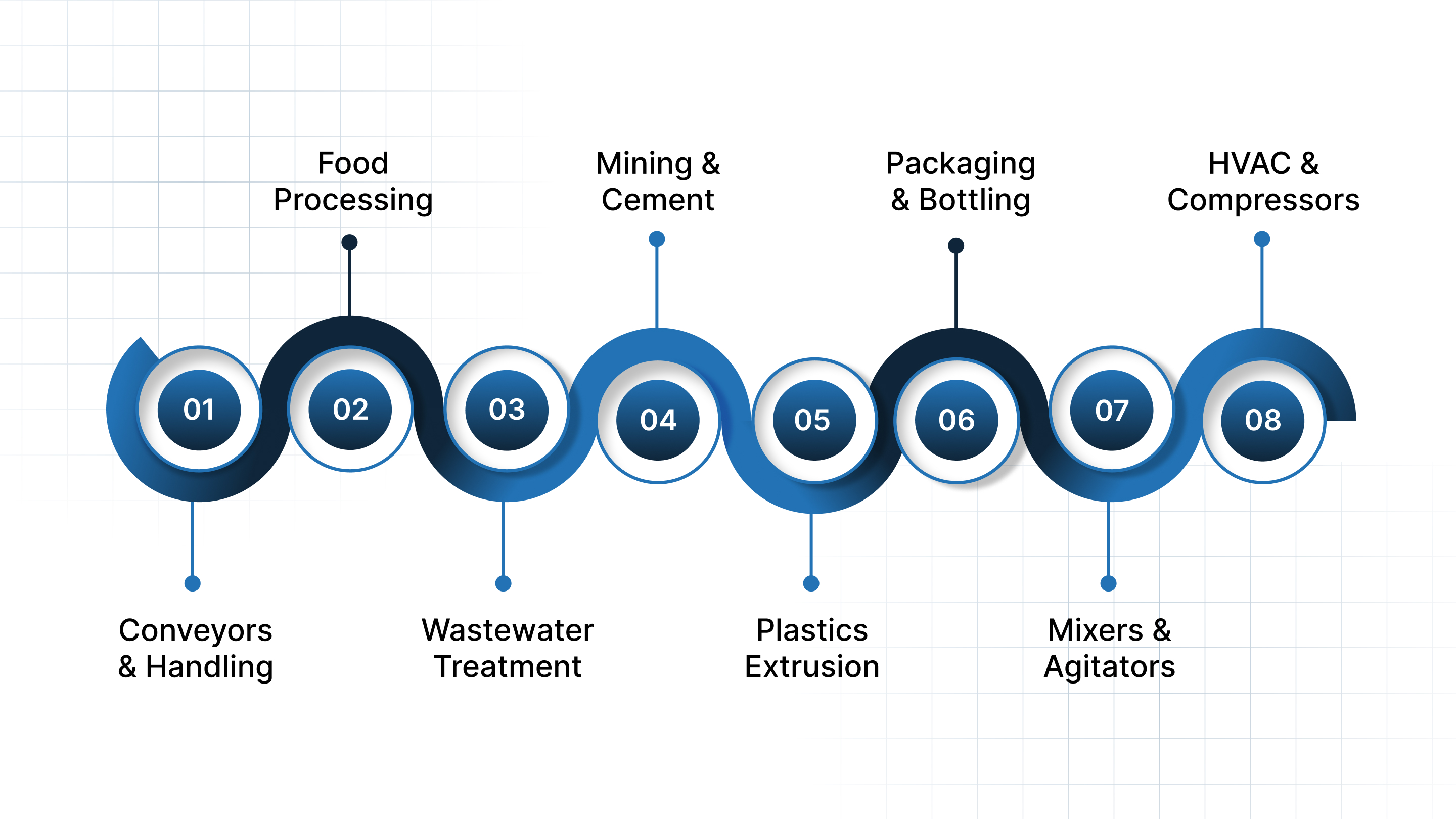
Torque-reduction gearboxes support equipment that must start under resistance, handle fluctuating loads, or maintain slow, stable motion for long duty cycles. These applications show where the right reducer makes a measurable difference in uptime and performance.
Conveyors and Material Handling: Bulk loads create drag at startup. Gearboxes provide the torque needed to move material smoothly and prevent strain on the drive motor.
Food & Beverage Processing: Mixers, augers, and conveyors work with dense or sticky products. They rely on strong low-speed torque to keep motion steady across each batch.
Wastewater Treatment and Pumping Stations: Clarifiers and aeration systems face high resistance from sludge and changing flow. Torque reduction helps these units run without mechanical shock or overload.
Mining, Cement, and Aggregates: Crushers, screens, and heavy conveyors operate under severe impact loads. Robust reducers deliver the torque required for consistent output and fewer breakdowns.
Plastics Extrusion: Extrusion screws need controlled force to push melted material through dies. A torque-rich reducer stabilizes throughput and protects the motor.
Packaging and Bottling Lines: Indexers and filling systems require steady rotational force at predictable speeds. Gearboxes support smooth, repeatable motion through every cycle.
Industrial Mixers and Agitators: Viscous materials create high shaft resistance. Torque reduction keeps the mixer turning at the required speed without overheating the motor.
HVAC, Blowers, and Compressors: These systems need controlled torque during startup and stable RPM during continuous use to avoid vibration and premature wear.
Manufacturers, integrators, and maintenance teams often rely on suppliers like Midwest Power Products for reducers suited to their load, duty cycle, and mounting needs, ensuring each application runs with the right torque profile from day one.
Efficiency and Design Considerations in Torque Reducers
Torque reducers must match the load, duty cycle, and mounting conditions of the machine. The points below show the factors engineers review before selecting a unit.
Efficiency differences: Worm reducers have lower efficiency due to sliding contact between gears. On the other hand, Helical and bevel reducers offer higher efficiency and smoother power transfer.
Heat generation: High ratios or continuous operation produce heat. Gear materials, lubrication, and housing design help manage temperature.
Backlash: Clearance between gear teeth affects positioning accuracy. Low-backlash designs are preferred in indexing, robotics, and packaging.
Wear patterns: Misalignment, poor lubrication, or overload create uneven wear. Correct shaft alignment and scheduled lubrication extend service life.
Load types (radial vs axial): Gearboxes must handle the direction of applied forces. Shaft and bearing design determine how well the reducer supports each load type.
Duty cycles: Continuous, intermittent, or start-stop duty affects gear selection. Higher duty cycles require stronger gearing and better thermal capacity.
Once the key design factors are clear, the focus shifts to selecting a reducer that can handle the required load, speed, and operating conditions.
How to Choose the Right Torque Reduction Gearbox
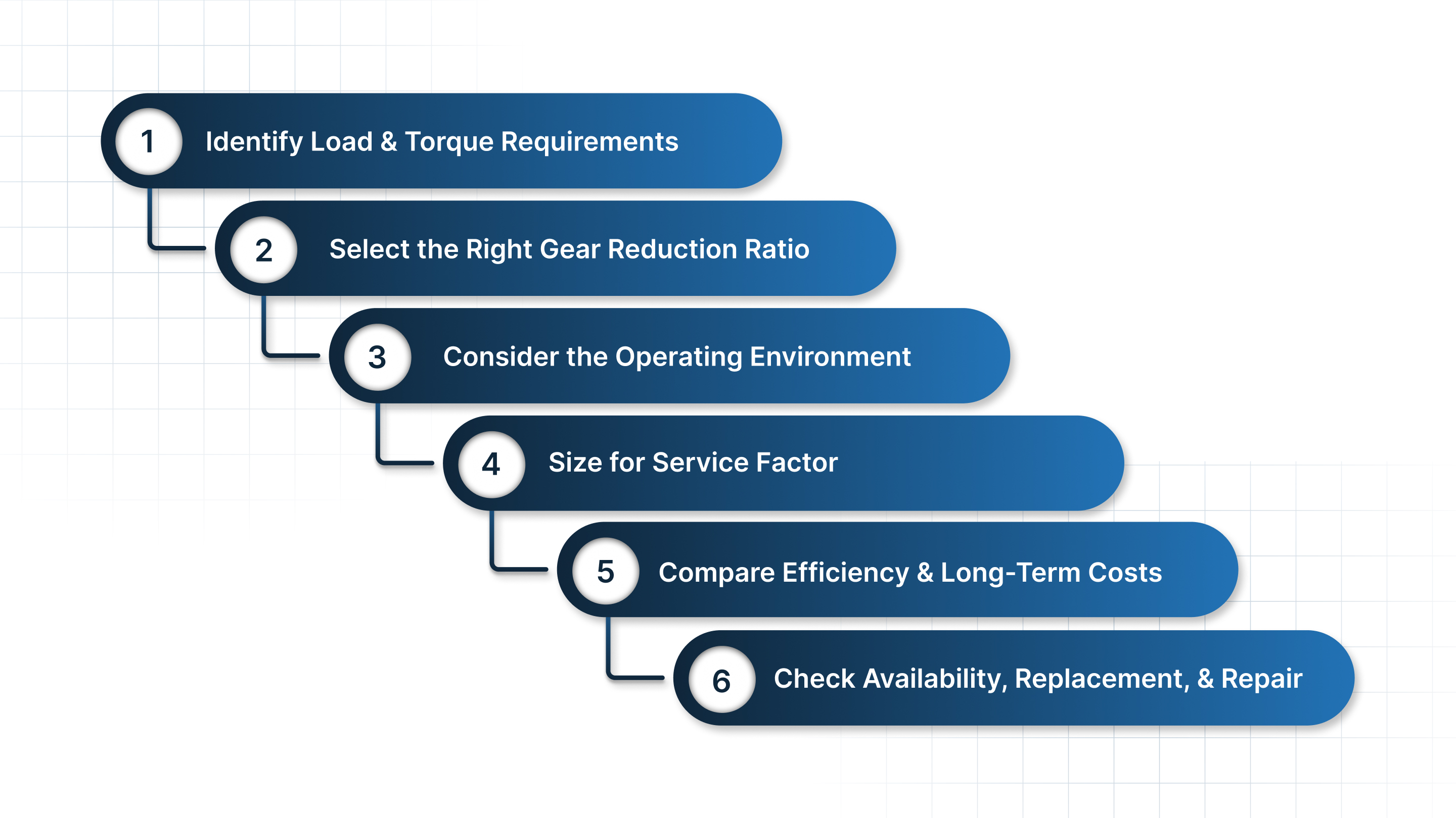
Selecting a reducer starts with understanding the machine's load and duty conditions. The steps below outline the checks most engineers follow when sizing a new unit or replacing an existing one.
Step 1: Identify Load and Torque Requirements
Break the load into specific torque values:
Breakaway torque: The force needed to start the machine under load.
Continuous torque: The torque required to keep the machine turning during steady operation.
Shock loads: Impact or irregular loads common in crushers, feeders, and mixers. Gearboxes for these applications need stronger gear sets and bearings.
Step 2: Select the Right Gear Reduction Ratio
Match motor speed to the required output speed.
Basic ratio formula: Input RPM ÷ Output RPM = Ratio
Example: A 1750 RPM motor running a conveyor at 60 RPM needs a ratio near 29:1.
Step 3: Consider the Operating Environment
The housing, seals, and lubrication strategy must fit the site conditions.
Washdown: Stainless or epoxy-coated housings reduce corrosion.
High or low temperature: Thermal capacity and lubricant grade must match.
Dust, slurry, or chemicals: Mining and wastewater sites need stronger seals and filtration.
Step 4: Size for Service Factor
Service factors help account for duty severity.
AGMA tables guide the factor based on load type, daily operating hours, and shock level.
Higher service factors extend gearbox life in start-stop or impact-heavy applications.
Step 5: Compare Efficiency and Long-Term Costs
Helical and bevel reducers often provide higher efficiency and lower energy losses than worm designs. Long-term cost includes lubrication intervals, heat management, and bearing life.
Step 6: Check Availability, Replacement, and Repair
A suitable gearbox should be easy to source and maintain across its service life. Teams often work with suppliers who can provide replacements, rebuilds, or part matches on short notice.
Midwest Power Products supports this process with 24/7 and same-day service for repair, replacement, or complete rebuilds of gear motors and drives.
Conclusion
Torque-reduction gearboxes help machines start smoothly, manage heavy loads, and maintain stable output across long duty cycles. Correct sizing, in terms of torque, ratio, environment, and service factor, reduces motor stress and extends equipment life.
Many teams rely on suppliers who can match these needs quickly and support repairs when downtime is costly. Midwest Power Products offers a wide range of reducer types along with 24/7 same-day service for repair, replacement, and rebuilds.
If you need guidance on selecting or sourcing a gearbox, contact our team for assistance with specifications and part matching.
FAQ
1. What does a torque reduction gearbox actually do?
It reduces motor speed through a gear ratio, which increases output torque. This allows machines to start under load and handle higher resistance without overloading the motor.
2. How do I calculate the gear reduction ratio for my application?
Divide motor RPM by the desired output RPM. For example, 1750 RPM to 60 RPM requires a ratio of about 29:1.
3. Which gearbox type gives the highest torque density?
Planetary gearboxes deliver the highest torque in the smallest footprint by distributing load across multiple gears.
4. Why does my gearbox run hot during operation?
Common causes include insufficient lubrication, overload, poor alignment, or a gearbox with low efficiency (such as certain worm designs).
5. How often should industrial gearboxes be lubricated?
Intervals depend on gear type, load, and environment. Most units require scheduled oil changes based on service hours and operating temperature.