Unplanned downtime is one of the most expensive problems in industrial operations. Studies show manufacturers lose more than $50 billion per year to unexpected failures. When the failure involves a gearbox, especially a high-torque reducer driving a conveyor, mixer, clarifier, or lift, the financial impact compounds quickly.
The industrial gearbox market is now a $30–33 billion global industry, growing steadily as plants modernize equipment and replace aging drives. Gear reducers have become operational assets, not just mechanical parts, and selecting the wrong reduction ratio can lead to overheating, torque loss, stalled starts, and premature failure.
This guide explains gear reduction ratios in clear, practical terms: how they work, how different gearbox types deliver their ratios, and how to calculate or verify the one your application truly needs.
Key Takeaways
Gear reduction ratios determine output speed and torque, making them central to how conveyors, mixers, clarifiers, and lifts perform in real operating conditions.
Different gearbox types (helical, worm, planetary, bevel, SMSR) offer different ratio ranges, efficiencies, and torque behaviors, so ratio alone isn’t enough to size a reducer correctly.
Calculating ratios is simple (input rpm ÷ output rpm), but interpreting them requires understanding efficiency losses, breakaway torque, service factor, and duty cycle.
Choosing the wrong ratio drives heat, stalls, inefficiency, and premature failure, especially in heavy-load or low-speed applications common in wastewater and material-handling environments.
Midwest Power Products helps teams get ratios right the first time with expert guidance, 50+ brands, rebuild services, and fast turnaround during downtime events.
Gear Reduction Ratio: What Is It?
A gear reduction ratio describes how many times the input shaft of a gearbox must rotate to produce one rotation at the output shaft. In simpler terms, it tells you how much the gearbox slows down the speed and multiplies the torque.
For example, a 10:1 reduction ratio means the input shaft (usually the motor) turns ten times for every one rotation of the output shaft. The output speed becomes lower, but the torque increases, making it possible to move heavier loads, start under high resistance, or maintain controlled motion at low speeds.
Why Gear Reduction Exists in the First Place
Electric motors naturally run fast: commonly 1,750 rpm or 3,450 rpm in industrial environments. Most equipment, however, does not operate anywhere near those speeds:
Conveyors often run between 20–80 rpm
Clarifiers can turn as slowly as 1–3 rpm
Thick sludge mixers may operate at 10–30 rpm
Bucket elevators and screw conveyors require lower, controlled speeds to prevent overload
A reducer bridges this gap. It converts the motor’s high speed into the low, usable shaft speed your application actually needs.
Now that the concept of a gear reduction ratio is clear, it is time to look at the gearbox types that deliver these ratios and how each performs under real industrial conditions.
Also Read: Gear Reducer Use Cases & Applications
Common Gearbox Types and Reduction Ratios They Offer
Every gearbox type achieves reduction differently, and each comes with its own torque capacity, efficiency range, ratio limits, and ideal applications. Choosing the right reducer begins with understanding how these designs behave under real load conditions.
Below is a practical breakdown of the most common industrial reducer types and the ratios they typically provide.
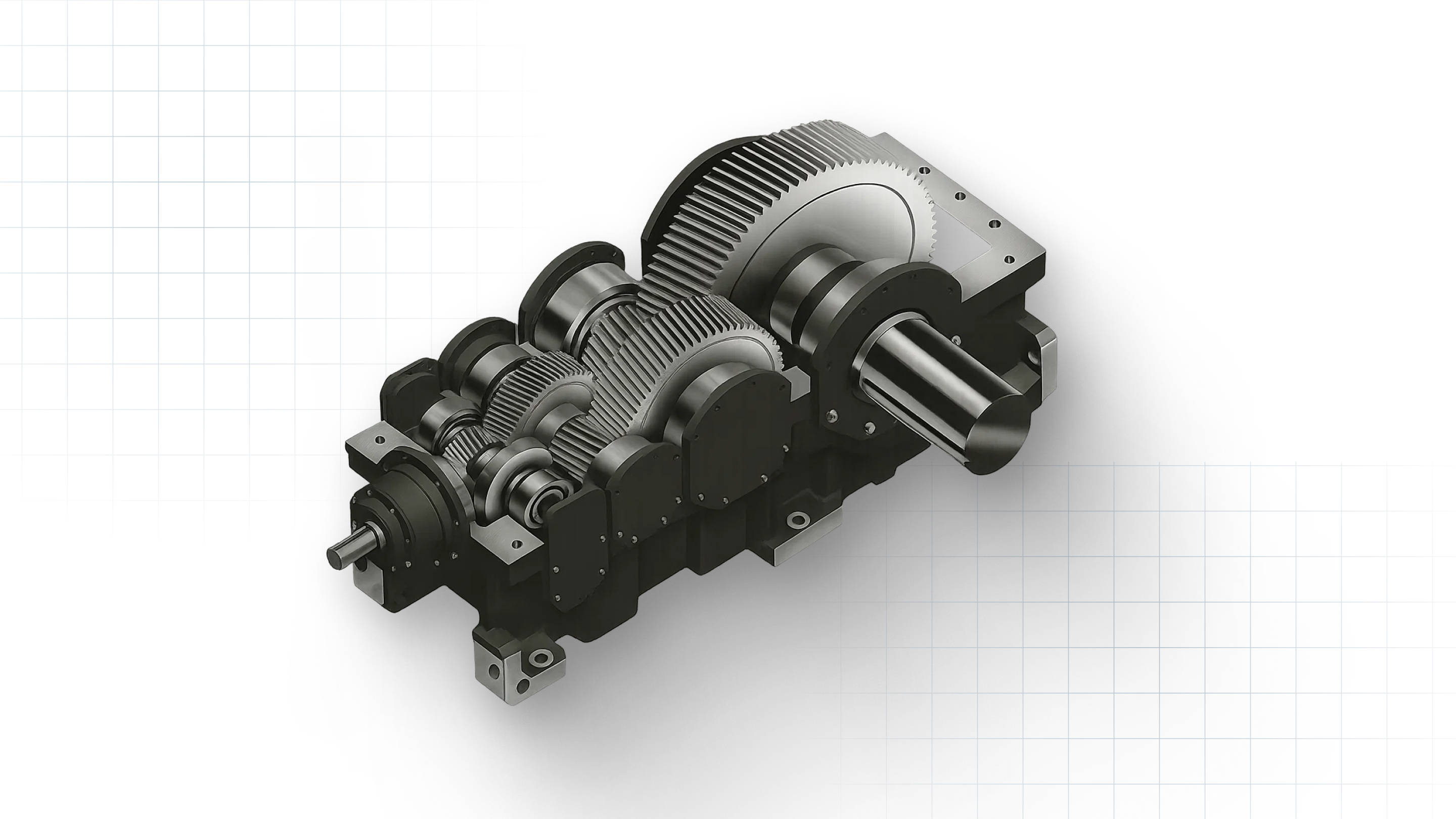
1. Helical Gear Reducers (Parallel Shaft & Inline Helical)
Typical Ratio Range:
Single-stage: ~3:1 to 5:1
Two-stage: ~10:1 to 25:1
Three-stage: up to ~80:1+
Why engineers use them:
Helical reducers are the workhorse of industrial drives with high efficiency, smooth operation, and strong torque capacity. Their angled teeth provide constant, quiet contact, making them ideal for continuous-duty applications.
Where they’re used:
Packaging and material-handling conveyors
OEM machinery
Pumps and blowers
Mixers that need steady torque and low noise
Key advantage: High efficiency (often 95%+ per stage) means less heat and lower energy cost than worm drives.
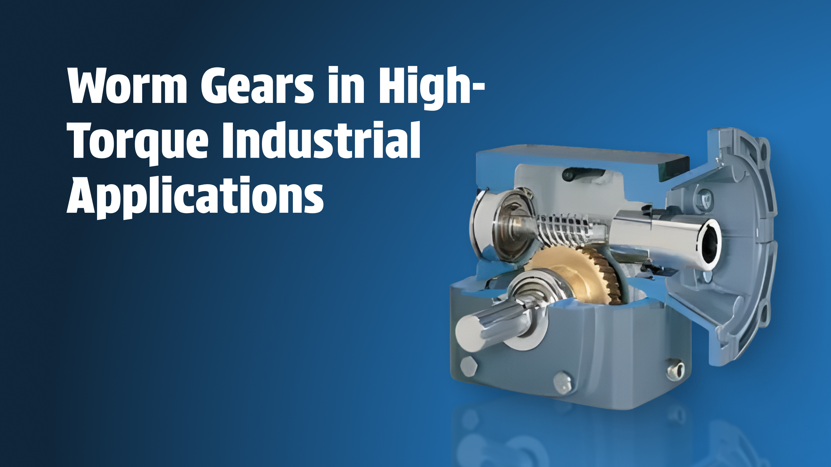
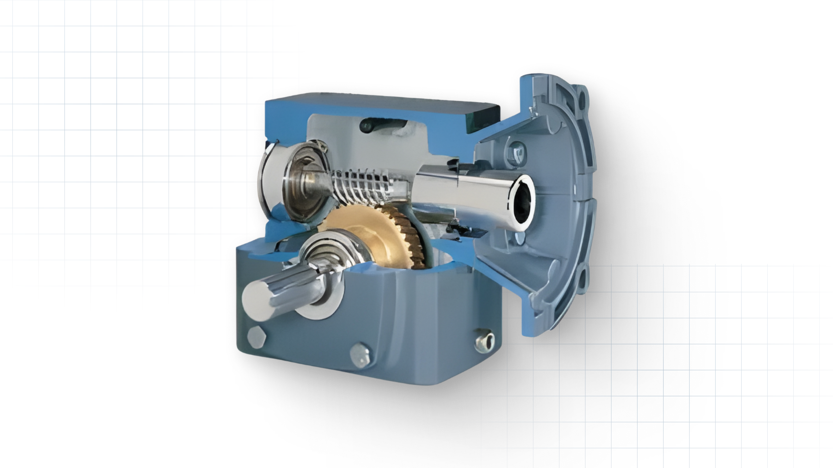
2. Worm Gear Reducers (Right-Angle Worm Drives)
Typical Ratio Range:
Single-stage: 5:1 to 70:1
Double reduction: 100:1 to 250:1+
Why engineers use them: Worm gearboxes deliver high reductions in compact footprints, often at lower upfront costs. Their sliding tooth contact allows self-locking behavior at higher ratios: useful in lifts, positioning systems, and applications where backdriving is unsafe.
Where they’re used:
Wastewater mixers, clarifiers, sludge equipment
Conveyors needing controlled, moderate speeds
Heavy adjustable mechanisms that must resist backdriving
Key trade-off: Lower efficiency (as low as 50–90% depending on ratio) and higher heat generation, which affects lifespan if misapplied.
3. Planetary Gearboxes (Epicyclic Drives)
Typical Ratio Range:
Single-stage: 3:1 to 10:1
Two-stage: 20:1 to 50:1
Three-stage: up to 100:1+
High-torque planetary systems: 200:1+
Why engineers use them: Planetary reducers offer extremely high torque density, low backlash, and excellent load distribution. They fit into tight spaces and maintain rigidity even at high torques.
Where they’re used:
Robotics and automation
Pick-and-place systems
High-precision conveyors
Industrial equipment requiring high torque in compact space
Key advantage: High efficiency and torque output for their size, often outperforming worm or helical units in weight-to-torque ratio.
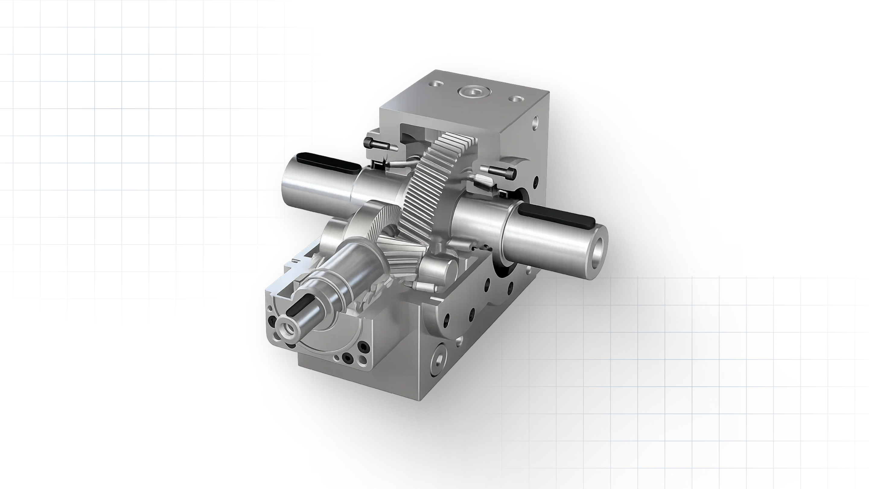
4. Bevel Gear Reducers (Right-Angle Bevel or Bevel-Helical)
Typical Ratio Range:
Single-stage bevel: ~1.5:1 to 6:1
Bevel-helical multi-stage: 10:1 to 200:1+
Why engineers use them: Bevel reducers transmit power at right angles with minimal loss and can be combined with helical stages for higher ratios.
Where they’re used:
Conveyors with changing shaft direction
Processing equipment with space constraints
Machinery transitioning from vertical motors to horizontal shafts
Key advantage: High efficiency and smooth motion in right-angle layouts where worm gears might overheat or lose efficiency.
5. Shaft-Mounted Gear Reducers (SMSR)
Typical Ratio Range:
~5:1 to 25:1
Why engineers use them: Popular in bulk material handling, SMSR units mount directly to the driven shaft, eliminating the need for couplings and extra alignment.
Where they’re used:
Screw conveyors
Belt conveyors
Bucket elevators
Key advantage: Simple installation, low maintenance, and strong torque for mechanical conveying systems.
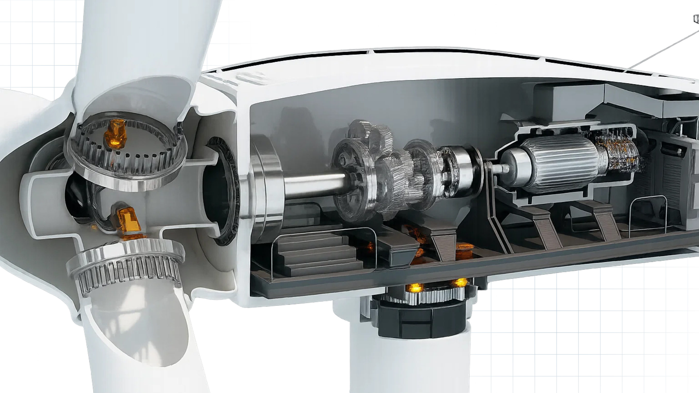
6. Multi-Stage Compound Gearboxes

Typical Ratio Range:
50:1 to 400:1+, depending on configuration
Industrial machinery often requires extremely low output speeds. Multi-stage assemblies combine worm, helical, or bevel stages to reach high reductions without overstressing a single gear mesh.
Where they’re used:
Water treatment equipment (clarifiers, scrapers)
High-torque mixers
Mining and heavy industrial equipment
Key advantage: Enables very slow shaft speeds (1–10 rpm) with the torque required to move heavy, high-friction loads.
With the major gearbox types and their typical reduction ranges in mind, the next step is understanding how to calculate and verify the ratio you need for your equipment.
Need guidance on selecting the right gear ratio? Contact Midwest Power Products today for a consultation and fast, reliable service.
How to Calculate and Interpret a Gear Reduction Ratio
Understanding how to calculate a gear reduction ratio and what that number really means helps you verify vendor quotes, double-check sizing decisions, and troubleshoot speed or torque issues before they become expensive downtime problems. Fortunately, the math is straightforward once you know what to look for.
1. The Basic Gear Reduction Formula
For a simple gear pair, the reduction ratio is:
Gear Reduction Ratio = (Input Speed) ÷ (Output Speed)
or
Gear Reduction Ratio = (Teeth on Driven Gear) ÷ (Teeth on Driving Gear)
Example: If the motor turns at 1,750 rpm and the reducer outputs 58 rpm, the reduction ratio is:
1,750 ÷ 58 ≈ 30:1
Meaning the output shaft rotates once for every 30 motor revolutions.
Why this matters: Even small miscalculations can dramatically change output torque and shaft speed, especially in conveying or mixing systems where speed control is critical.
2. Interpreting Gearbox Nameplates (The Practical Way)
Most industrial gear reducers list the overall ratio directly on the nameplate, like:
“R40” → ~40:1
“Ratio 25.6” → 25.6:1
“I = 15.8” → 15.8:1 (common on helical units)
“100:1” → common on multi-stage worm units
If multiple stages are used, the total ratio is the product of every stage:
Stage 1: 4:1
Stage 2: 5:1
Total ratio: 4 × 5 = 20:1
Tip for maintenance teams: When retrofitting legacy equipment, be aware that nameplates may be missing. In that case, measuring input and output shaft speeds with a handheld tachometer gives a quick ratio estimate on the floor.
3. How Ratio Affects Torque
A reducer multiplies torque by roughly the same factor that it reduces speed, minus losses from efficiency.
Output Torque ≈ Input Torque × Ratio × Efficiency
So a 2 HP motor producing 6 lb-ft of torque at the shaft, paired with a 40:1 helical reducer (approx. 95% efficient), produces:
6 × 40 × 0.95 ≈ 228 lb-ft at the output.
With a worm gearbox of the same ratio (approx. 70% efficient), output torque would be significantly lower.
This is why ratio + gearbox type must always be evaluated together.
4. Matching Ratio to Required Output Speed
A practical workflow:
Identify motor base speed (e.g., 1,750 rpm).
Determine required output rpm from process specs (e.g., 35 rpm for a conveyor).
Divide motor speed by required speed:
1,750 ÷ 35 ≈ 50:1
Select the closest catalog ratio (e.g., 50:1, 48:1, or 56:1).
Verify torque, service factor, and thermal ratings.
Why this is critical: If the ratio is even slightly off, the equipment may run too slow for throughput or too fast and overload bearings, chains, flights, or paddles.
5. Using VFDs With Reduction Ratios
Variable Frequency Drives (VFDs) change motor speed electronically, but they cannot replace proper gearbox sizing.
A good rule of thumb: Use VFDs for fine speed control around a correctly sized reduction ratio, not as a substitute for ratio selection.
Too much VFD turndown → insufficient torque at low frequencies
Too much VFD speed-up → cooling issues, shortened motor life
Correct ratio + VFD gives you speed flexibility without sacrificing reliability.
Once you understand how ratios are calculated and interpreted, the next step is knowing how to choose the correct reduction ratio for your specific conveyor, mixer, clarifier, or other industrial application.
If you're unsure whether your current gear reduction ratio is the best choice for your equipment or if you're dealing with legacy systems that need a ratio check, Midwest Power Products is here to help. With expert recommendations, quick turnaround, and a vast inventory, we ensure your machinery keeps running smoothly. Book a free consultation now.
Also Read: Why Choose Electra Gear Aluminum Gear Reducers?
Choosing the Right Gear Reduction Ratio for Your Application
Selecting the right gear reduction ratio is more than matching numbers on a spec sheet. The ratio directly determines how your equipment behaves under load: how smoothly it starts, how much torque it delivers, how efficiently it runs, and how long the gearbox will survive in real operating conditions.
The goal is to choose a ratio that aligns with actual process demands, not just what was installed decades ago.
Below is a practical, engineering-grounded framework your maintenance and operations teams can use.
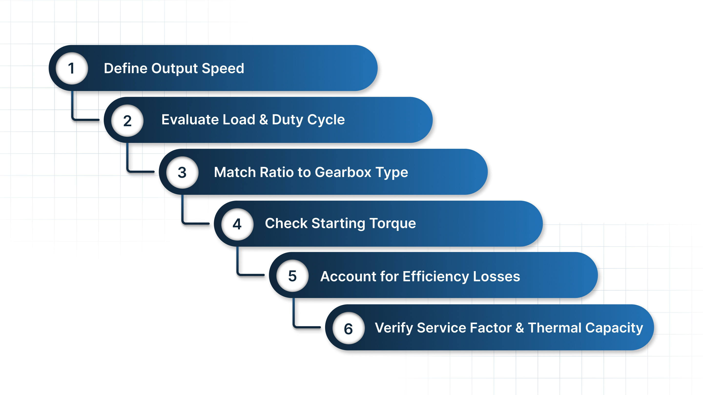
1. Start With the Required Output Speed
Every application has a target working speed. Begin there, not with the gearbox catalog.
Typical industrial examples:
Packaging conveyors: 20–80 rpm
Screw conveyors: 30–60 rpm
Wastewater clarifiers: 1–3 rpm
Mixers and agitators: 10–40 rpm
Bucket elevators: 5–20 rpm
Once you know the required output rpm, calculate the ideal ratio from motor speed (usually 1,750 rpm or 3,450 rpm).
Formula:
Ratio ≈ Motor Speed ÷ Required Output Speed
This sets the baseline. Everything else fine-tunes your decision.
2. Evaluate Load Type and Duty Cycle
Two applications with the same target rpm may need very different ratios because their load characteristics differ.
Steady, uniform loads
(e.g., belt conveyors, blowers, simple pump drives)
→ Can often use lower ratios and more efficient gear types (helical or parallel shaft).
High-torque, high-friction, or start-stop loads
(e.g., mixers, sludge thickeners, bucket elevators)
→ Often require higher ratios for torque multiplication to avoid stalling or overheating motors.
Slow, high-resistance applications
(e.g., scrapers, clarifiers, indexing equipment)
→ Commonly use combinations of helical + worm or multi-stage reducers for extremely low speeds.
The more shock and resistance in the system, the more carefully the ratio must be sized.
3. Match the Ratio to the Right Gearbox Type
Two reducers with the same ratio can behave very differently:
Helical reducer at 40:1
High efficiency
Smooth operation
Long service life
Ideal for continuous-duty conveyors
Worm reducer at 40:1
Compact and cost-effective
Lower efficiency
Generates more heat
Useful where self-locking is needed
Planetary reducer at 40:1
High torque in a small footprint
Low backlash
Excellent for precision or high-load applications
Ratio ≠ performance.
Ratio + gear type = correct performance.
4. Consider Starting Torque and Breakaway Requirements
Breakaway torque is the torque needed to start the load moving.
This is often 2–3× the running torque in:
Mixers with settled solids
Screw conveyors packed with material
Clarifiers that start under heavy load
Vertical conveyors or lifts
If the ratio is too low, the system may stall or overload the motor on startup, even if it runs fine afterward.
Selecting a higher ratio gives the gearbox more mechanical advantage, helping overcome breakaway torque safely.
5. Account for Efficiency Losses
Higher ratios and certain designs (mainly worm drives) reduce efficiency.
Approximate efficiency ranges:
Helical: 94–98% per stage
Planetary: 90–97%
Worm: 50–90% depending on ratio
Lower efficiency means:
More heat
Lower delivered torque
Shorter lubricant life
Higher operating cost
If you need a high reduction ratio but also care about efficiency, combine helical + bevel or helical + planetary stages rather than choosing a multi-stage worm.
6. Verify Service Factor and Thermal Capacity
A ratio that works on paper may fail early in the field if service factors aren’t accounted for.
Check:
Mechanical service factor (shock loading, reversing, duty cycle)
Thermal capacity (especially for worm reducers at high ratios)
Overhung and thrust load capacity
Cycle frequency (start/stop cycles per hour)
A properly selected ratio should keep the reducer within safe torque and temperature thresholds.
How Midwest Power Products Helps You Get Gear Reduction Ratios Right
Getting the right gear reduction ratio requires the correct gearbox type, proper torque matching, and an understanding of real-world load conditions. Midwest Power Products supports engineers, maintenance teams, and OEMs by helping them select, source, or rebuild gear reducers that match the exact speed, torque, and duty cycle their applications demand.
Wide selection of brands and configurations: Midwest Power Products distributes gear reducers and gearboxes from 50+ trusted manufacturers, giving you multiple options instead of forcing a single brand or model.
Application-driven engineering expertise: Their team helps plants choose the appropriate ratio and gearbox type (helical, worm, bevel, planetary, or multi-stage) based on actual load requirements, not assumptions.
Repair, rebuild, and legacy support: If the original gearbox is worn out, obsolete, or missing a nameplate, Midwest Power Products can repair, rebuild, or source the correct replacement without guesswork.
Emergency turnaround when downtime matters: With same-day shipping and rapid-response support, Midwest Power Products helps plants recover quickly from unexpected gearbox failures.
Conclusion
Gear reduction ratios may look simple on paper, but the right ratio determines how well your equipment starts, runs, and survives under real operating conditions. When the ratio is misapplied, even slightly, the result is slowdowns, overheating gearboxes, poor torque delivery, higher energy use, and unnecessary downtime.
By understanding how ratios work, how different gearbox types behave, and what pitfalls to avoid, maintenance teams and engineers can make smarter decisions that protect both uptime and budget.
And when you need support beyond the theory, having a partner who specializes in gear reducers and industrial power transmission makes all the difference.
Midwest Power Products helps plants and OEMs get reduction ratios right the first timewhether you need a replacement unit, a custom gearbox, help verifying ratios in legacy equipment, or rapid turnaround during an equipment failure.
Need help selecting the right reduction ratio for your next project? Contact Midwest Power Products today for expert guidance and fast support.
FAQ
1. What is the difference between gear ratio and reduction ratio?
They refer to the same concept, but in industrial applications, reduction ratio specifically describes ratios where the output speed is lower than the motor speed. A “gear ratio” can refer to speed increase or decrease, while a “reduction ratio” always means output rpm is reduced and torque is increased.
2. How do I know if my gearbox ratio is correct for my application?
Verify three things:
The output speed matches your required process speed
The gearbox can deliver enough torque (including breakaway torque)
The reducer stays within safe thermal and service-factor limits
If any of these are off, the ratio may be incorrect even if the equipment still runs.
3. Can I use a VFD instead of changing the reduction ratio?
A VFD can fine-tune speed, but it should not replace a proper mechanical reduction. Heavy-duty, high-torque, or low-speed applications depend on a correct ratio. Using only a VFD can lead to overheating, weak torque, or startup failures.
4. What happens if a reduction ratio is too high for my equipment?
A ratio that’s too high will slow the output excessively, reduce throughput, and may cause the motor to operate inefficiently. Conversely, too low a ratio may not provide enough torque, leading to stalling or premature gearbox failure.